
Introduction
The demand for reasonably priced, long lifetime solar simulators with broad spectral coverage and low spectral deviation has never been greater. The expansion of the solar industry to meet the world’s energy usage coupled with the need for engineered light for materials testing, photochemistry, biological, multispectral, and hyperspectral applications has sparked the development of sophisticated broad-spectrum illumination. In fact, with society’s move toward environmentally friendly light sources, light-emitting diodes (LEDs) have emerged as a superior alternative to arc lamps and lasers. Innovations in Optics, Inc. [IOI] has been uniquely positioned for over three decades to address these needs with new designs, like the LumiSun-50TM (Patent Pending), that incorporate the latest advancements in LED die and engineering technology. As pioneers in high-powered LED technology, IOI has been pushing boundaries to maximize photon delivery with uniformity, stability, and longevity. IOI’s unique capabilities in imaging and non-imaging optical design, thermal analysis, and electronics technology coupled with rapid improvements in LED die technology have enabled optimized illumination for a broad spectrum from Ultra-Violet [UV] through Near-Infrared [NIR]. Thus, IOI LED solar simulators offer greater efficiencies and lower operating costs over traditional technologies.
Overview
In this white paper, we will highlight important considerations in the design and selection of solid-state solar simulators that provide outstanding spectral match and high spectral coverage with long lifetime.
Specifically, this includes:
(1) Advantages of LED solar simulators
(2) Spectral coverage and deviation vs. class designation
(3) Thermal management for temporal stability and long life
(4) Importance of uniformity
(5) Applications
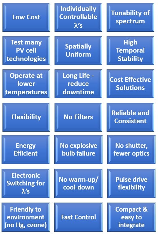
Conventional solar simulators have often been configured with Xenon short-arc lamps, QTH lamps, and metal halide discharge lamps. Yet, solid state sources such as LEDs offer numerous advantages over lamps (Appendix A). Solar simulators configured with LEDs are more energy efficient and support ongoing green initiatives – important considerations as global energy demand is expected to increase, and renewable solar energy helps mitigate climate change.1 LEDs are more environmentally friendly than lamps which contain mercury, create ozone, and emit UVC. The spectral output of LEDs is more stable over long lifetime than arc lamps and so a more reliable and consistent simulation of the sun is possible. Unlike arc lamps, there are no explosive bulb failures with LEDs, they operate at lower voltage and temperatures, and have longer service life.2
Thus, down-time is lessened, and productivity increased. LED illuminators are only ‘on’ during exposure; there is no warmup, cool down, shutters, filters, or high-voltage igniters that lamps require. The relatively narrow spectrum of LEDs allows for the spectrum to closely mimic the effects of atmospheric absorption which is difficult to do with filters. In addition, each individual wavelength can be controlled electronically within microseconds to adjust the spectrum according to the user’s location or application. Such advantages of LEDs all lead to lower cost of ownership.
When selecting an LED solar simulator, it is important to consider how well it mimics the sun and the requirements for a specific application. Simulators can run continuously or flash for short periods of time with defined frequency and shape. They can also allow user-set spectral profiles over discrete wavelength ranges. There are significant differences in simulator size, optical power output (1 Sun = 1000 W/m2), spectrum, field of illumination, uniformity, and stability. Thus, solar simulators are most often categorized with Class ratings per IEC specifications (IEC 60904-9, 60904-3). See Table 1. There are three classes: Spectral Match, Spatial Non-Uniformity, and Temporal Instability. These are rated with the best performance as A+ and then down to classification C. For all but A+, which is over a broader range of 300 – 1200nm, the wavelength range is 400 – 1100nm.3
|
Classification per IEC |
Minimum l Range for Evaluation (nm) |
Spectral Match to all Intervals (%) |
Spatial Non-Uniformity of Irradiance (%) |
Temporal Instability (%) |
|
|
Short Term (STI) % |
Long Term (LTI) % |
||||
|
A+ |
300 – 1200 |
87.5 to 112.5 |
1 |
0.25 |
1 |
|
A |
400 – 1100 |
75 to 125 |
2 |
0.5 |
2 |
|
B |
400 – 1100 |
60 to 140 |
5 |
2 |
5 |
|
C |
400 – 1100 |
40 to 200 |
10 |
10 |
10 |
Table 1: Definition of solar simulator classifications per IEC 60904-9 Edition 3.0 2020-09.
A solar simulator with Class A+ ratings and 1.2 Suns, like IOI’s LumiSun-50TM, gives the operator more flexibility in spectrum and is superior in uniformity and temporal stability. Figure 1 below compares the solar spectrum for AM1.5G to the IOI LumiSun-50TM measured spectrum. The 35 LED wavelengths selected for LumiSun-50TM result in excellent spectral match over the broadest range of 300 to 1200nm (Class A+).
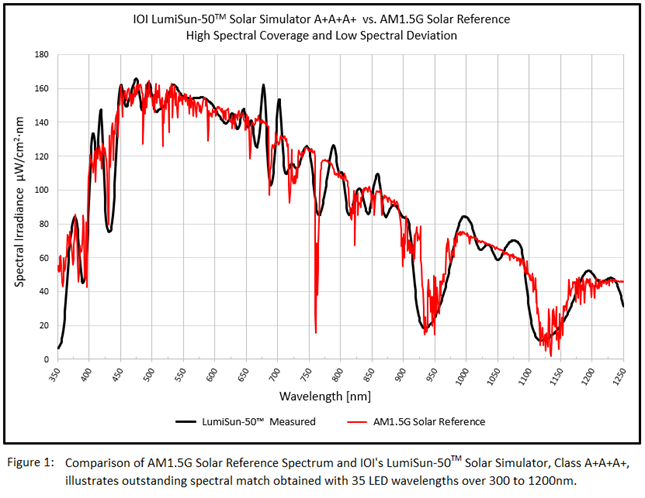
Buyer beware though. Class does not tell the whole story since each classification is averaged over six broad bands of wavelengths (Table 2). Fortunately, LumiSun-50TM goes beyond Class.
|
Wavelength Range (nm) |
% of total irradiance in l range 300 – 1200nm |
Cumulative Integrated Irradiance (%) |
|
|
1 |
300 to 470 |
16.61 |
16.61 |
|
2 |
470 to 561 |
16.74 |
33.35 |
|
3 |
561 to 657 |
16.67 |
50.02 |
|
4 |
657 to 772 |
16.63 |
66.65 |
|
5 |
772 to 919 |
16.66 |
83.31 |
|
6 |
919 to 1200 |
16.69 |
100.00 |
Table 2: Global reference solar spectral irradiance distribution per IEC 60904-9 Ed. 3.0 2020-09 calculated over six wavelength bands
Perhaps even more critical are the parameters Spectral Deviation (low is best) and Spectral Coverage (high is best). The key question is – How well does the solar simulator match the entire solar spectral reference curve? The answer for LumiSun-50TM is ‘superior to competitors,’ but let us look quantitatively.
The IEC defines Spectral Coverage (SPC) and Spectral Deviation (SPD) for AM1.5 as the following:4
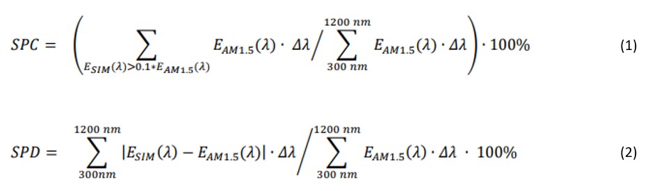
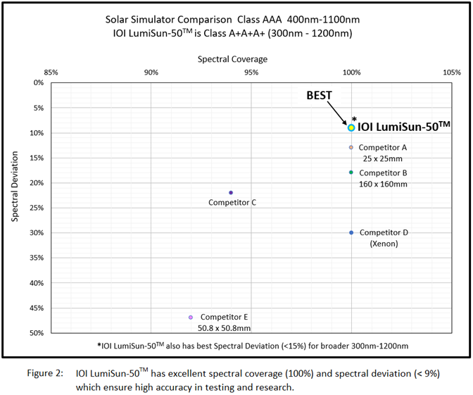
The total number of LEDs and wavelengths used in a solar simulator are of paramount importance in providing high SPC and low SPD and thus high accuracy in testing and research. For example, IOI’s latest version of LumiSun-50TM has a total of 76 LEDs with 35 different wavelengths that are controlled individually. Consequently, this enables a superior SPD of < 9% over 400-1100nm compared to competitors’ 13%. See Figure 2. In addition, over a broader range of 350-1250nm, SPD is outstanding at < 12%. This is not accomplished easily and requires significant experience and expertise not only in LED die and wire bonding, but in optical, electrical, thermal, and mechanical design. Solar simulators are complex devices that require synergy from all engineering disciplines.
IOI’s patented technology enables close packed LED arrays mounted directly to the bare copper board and strategically wire bonded – all in-house operations done with bare LED die. Thus, IOI can maximize the density of the LED arrays, collect more light, and optimize the appropriate number of LEDs for each wavelength. Not all LED die are created equal; power, bandwidth, and tolerable drive current vary. However, with proprietary thermal management, IOI succeeds in boosting even the most meager performing LEDs while maintaining long lifetimes. In addition, LED technology continues to see advancements and there is a wide range of wavelengths available that allows increasingly accurate solar simulation. IOI specializes in acquiring and testing the best LEDs available worldwide.
Higher quality of engineered light equates to better and faster research. Thus, though applications vary in their needs, choosing an LED solar simulator with the lowest spectral deviation, highest spectral coverage, highest rating of A+A+A+, the ability to control the spectrum and to operate CW or pulsed affords researchers and experimentalists reliability, repeatability, precision, and accuracy in their measurements.
With more than three decades of experience in high power LED technology, including thermal analysis and control systems, IOI recognizes numerous factors in designing solar simulators that surpass competitors’ performance. A solar simulator with Class A+A+A+ (such as the IOI LumiSun-50TM) must meet IEC requirements for long-term temporal instability (LTI) < 1% and short-term instability (STI) < 0.25%.5 In fact, LumiSun-50TM exceeds A+ with STI < 0.1%. This translates to higher accuracy and repeatability for researchers.
With appropriate thermal management, LED die can be driven at higher currents, often up to 3A/die CW, to obtain more optical irradiance with high temporal and wavelength stability. This is particularly important for applications that wish to accelerate testing. What could be a year of testing can be reduced to weeks if there are enough Suns available (1 Sun = 1000 W/m2). In addition, tunable LEDs allow the user to tailor the overall spectrum to their needs and restrict the range of wavelengths and increase the number of Suns within a given band.
There are many considerations in achieving stability and lifetime for LED solar simulators. The selection of LED wavelengths, size of the LED die, voltage characteristics, polarity, efficiency, bandwidth, and behavior over time – all play an important role. Thermal management is critical. Increasing temperature has many adverse effects on LED performance. Peak wavelengths can shift which has serious consequences for testing with solar simulators. Table 3 illustrates the approximately 26% decrease in optical power, 10nm shift in peak wavelength, and increasing full-width-half-maximum [FWHM] with increasing board temperature for one red LED die at a fixed drive current of 1A. Longer wavelength LED die tend to experience greater loss and spectral shift with changes in junction temperature.
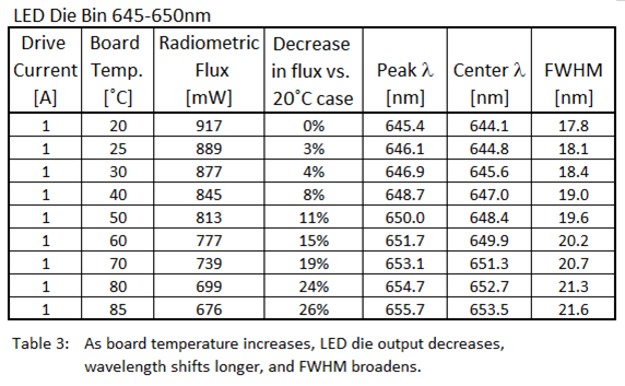
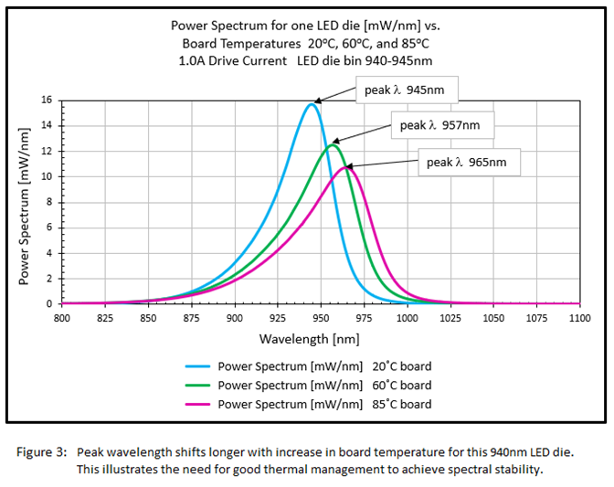
Figure 3 below shows the spectral shift as board temperature increases (indicative of LED die junction temperature increase). The 940nm LED die shifts by 20nm and FWHM broadens as board temperature increases from 20oC to 85oC. LED die and wire bonds can also experience stress with heating and cause catastrophic failure or decreased lifetime. Keeping the LED die junction temperature low (< 65oC) and stable extends the lifetime of the LEDs and minimizes spectral shifting. One rule of thumb is that for every 10˚C cooler junction temperature, LED die lifetime increases by a factor of two.
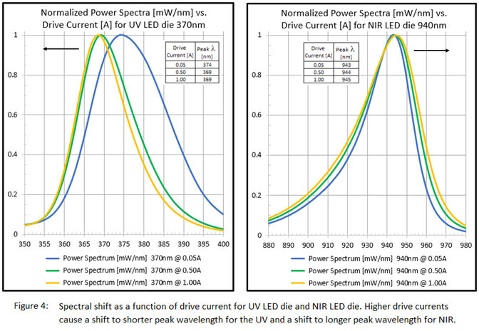
In addition to spectral shift from insufficient cooling, LED wavelengths shift longer or shorter under higher drive current depending upon the wavelength of the LED die. Figure 4 shows this shift for one UV LED die (shorter) and one NIR LED die (longer) under 0.05A, 0.50A and 1.00A drive currents for a stable board temperature of 20oC.
The trick is to cool efficiently, with low footprint, ease of operation, and low cost. The solar simulator should be simple to use and easy to maintain. The board must be designed and the LED die mounted optimally to conduct heat away quickly. In addition, the manufacturing process involves numerous steps and quality control. Location of the LED die is a well-analyzed process since quality of the optical output and manufacturability for high volume production are important. Complex auto die bonder programs, particularly for multi-wavelength light engines such as solar simulators, support the intricacy of LED die arrays unique to IOI.
Along with LED die and wire bonding optimizations, there are associated thermal considerations for optimizing optical power output, stable spectrum, and lifetime of the LED die. With expertise in thermal management comes the ability to use a large number of LED die, as with the LumiSun-50TM. This not only improves spectral match and uniformity, but allows operation at or below rated currents for each LED die to promote long life while maintaining high optical output such as LumiSun-50TM’s 1.2 Suns.
Thermal analysis is key in determining the type of system cooling necessary to keep LED die junction temperature low. Software such as SolidWorks FLOW uses computational fluid dynamics (CFD) to model, optimize, and predict thermal performance for complex systems. As was the case for IOI’s LumiSun-50TM, this analysis is highly reliable with accurate modeling of constituent components and material properties. Figure 5 is an example of thermal analysis by IOI which incorporates thermo-electric coolers (TECs), high efficiency heat sinks, forced convection, and ambient temperature changes.
Furthermore, precise modeling and mechanical design of enclosures are important as is the electrical design of the driver board and system. Thus, IOI performs all optical, mechanical, thermal, and electrical design and analysis in-house to ensure a cohesive, high quality system.
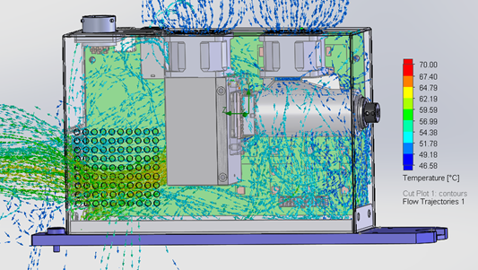
Figure 5: Example of complex thermal analysis with SolidWorks FLOW used routinely by experts at IOI to ensure stable temperature and long life for LED illuminators.
Thermal management can also include liquid heat exchangers which IOI uses frequently for its UV LED DMD Illuminator. However, for LumiSun-50TM, IOI has integrated TEC temperature control to ensure superior performance for spectral intensity stability and a predicted lifetime of 20,000 hours (L70). Specifically, the TEC can stabilize temperature to prevent spectral shift near both CdTe and Si band edges, and those of other material systems in development.
Spatial uniformity is an important parameter for solar simulators since it allows consistent testing across an entire sample. The IEC defines it in terms of non-uniformity, and lower values < 1% as in Class A+ simulators like LumiSun-50TM represent excellence.6 Solar simulators vary in the size of the illumination field and can range from less than 50x50mm to larger areas 100x100mm or over 300x300mm.
Whatever the application or size, it is essential to recognize over what area the device meets the advertised non-uniformity and the number of Suns (1 Sun = 1000 W/m2) associated with it. Some simulators have large area outputs, but only a subset of that area has low non-uniformity.
Furthermore, another crucial consideration, especially for testing of small samples or subsets within a larger sample, is related to how uniformity is defined. Most solar simulators have an accuracy problem for very small samples, but LumiSun-50TM does not. The IEC document 60904-9 Ed. 3.0 2020-09 Section 3.9 defines spatial non-uniformity of irradiance as:
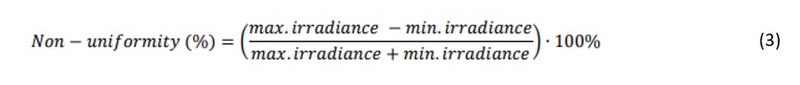
with a detector size specified in Section 5.3.2.3 not larger than 1/5 of the smallest dimension of the test area.6 Thus, a 5×5 grid has 25 detector areas. Any illumination within a given unit area may have poorer uniformity. The implication is that for test sample sizes smaller than the stated total area, the uniformity is uncertain and likely not within specification. For example, if you were to test a solar cell that is smaller than the total defined illumination area, then local fluctuations would not be averaged out. The user would be misled regarding the level of non-uniformity and their data would be compromised.
LumiSun-50TM does not have this issue and it has excellent performance for the smallest of solar cells or material samples.
Obtaining excellent uniformity requires extensive knowledge in optical design, thermal management, LED die technology, electrical design and control, mechanical design, and materials science. The main component of a solar simulator is the illumination source, and the optical design can be complex for multiple wavelengths. IOI maximizes the number of LED die for its illuminators and determines LED die position on the LED board to optimize uniformity.
Large numbers of LED die, like the 76 LED die in LumiSun-50TM and OEM versions, are selected to minimize structure near CdTe and Si band edges – important for solar cell testing (1100nm ~ 1.1eV = band gap of silicon). LED die exist beyond 1250nm and IR extensions of the spectrum could be useful. Consideration is given to system etendue, the size of the optics and overfill area tolerancing, homogenization of the light, and depth of focus. Figure 6 shows the minimal impact on uniformity vs. depth of focus for LumiSun-50TM which is designed for stability and ease of alignment. As expected, the intensity decreases as distance from nominal increases and the non-uniformity increases for smaller image sizes at closer distances for a fixed grid. Over a range of +/- 10mm distance from the nominal illumination plane, the non-uniformity changes by less than 5% and the intensity changes by less than 10% – all still within the A+ Class.
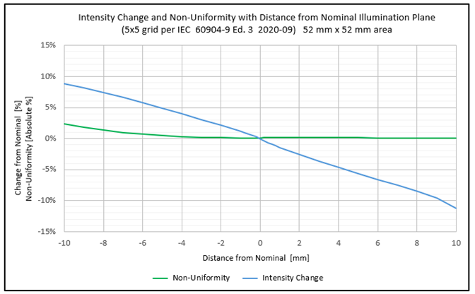
Figure 6: Illustrates minimal degradation of uniformity with distance from nominal image plane which eases alignment tolerances and improves measurement accuracy.
For multi-wavelength sources that span a broad range of wavelengths, e.g. 300 – 1250nm, the appropriate materials and coatings must be used to ensure no degradation from UV through IR over time. In addition, the characteristics of the LED die should be well known, and LED die should be life tested since failures of die can impact uniformity and spectral deviation. For example, LED die with higher forward voltage ratings generally produce more heat. Thus, it would be important to run them at lower current which could necessitate using multiple LED die at that wavelength to obtain the required output power and uniformity.
Not only does IOI’s LumiSun-50TM exhibit better than Class A+ non-uniformity for all wavelengths, but it is also Class A+ (< 1%) for each individual wavelength as well. This sets it apart from other solar simulators since this allows for more accurate measurements with all wavelengths illuminating uniformly across the entire sample. Figure 7 illustrates the measured non-uniformity (0.76%) over the entire illumination field of 50x50mm.
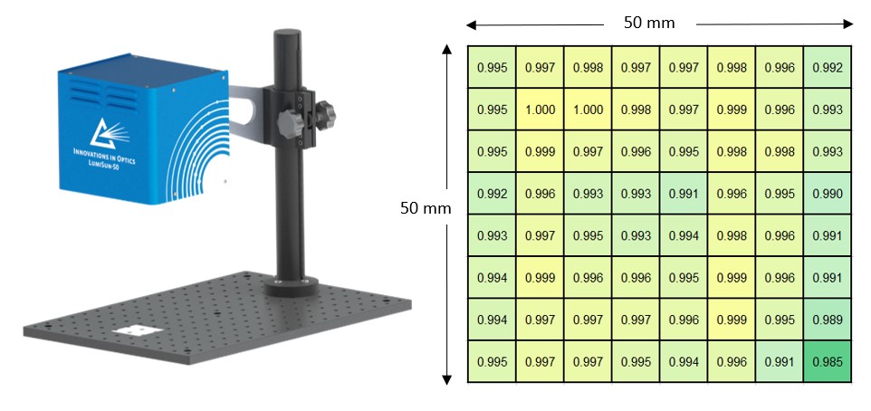
Figure 7: LumiSun-50TM performs better than Class A+ with measured non-uniformity 0.76% for all wavelengths and < 1% for each wavelength separately.
There is a multitude of applications which require “sun” exposure that wish to test indoors or in an accelerated fashion. Solar simulators are often used for qualification and research in solar cells (e.g. bifacial configurations and perovskite), materials testing such as sunscreen and plastics, and the study of light sensitive organisms, chemicals, and biological phenomena. Figure 8 offers a quick visual overview of solar simulator uses which rely on spectral stability, accuracy, and repeatability.
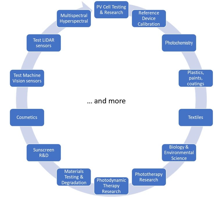
Figure 8: LED Solar Simulator Applications.
CONCLUSION
LED solar simulators offer a more efficient, low-cost alternative to arc lamp versions. Though they are complex devices that require synergy between all engineering disciplines, LED solar simulators are quickly replacing lamps. End-users should look for devices that offer spectrum flexibility, ease of operation, simple cooling schemes, and long operating life at a competitive price. The rapid development of LED die from UV to IR coupled with expert optical design, thermal management, and electrical control enable A+A+A+ performance with minimal spectral deviation. For example, the LumiSun-50TM by Innovations in Optics, Inc. [IOI] consumes < 75 Watts to produce 1 Sun of irradiance in a 50 x 50mm illumination field compared to over 300W required by Xenon arc lamps. Its thermoelectric temperature stabilization provides superior spectral intensity stability, and it exceeds Class A+ temporal instability. LumiSun-50TM can output 1.2 Suns as well with less than 1% non-uniformity, which helps speed degradation testing and produce accurate, repeatable results for researchers.
In addition, IOI’s patented and patent-pending technology is easily extendable to large area solar simulators and solar soakers.
The future of the world depends upon clean energy such as solar and non-toxic technologies. LED solar simulators are helping to pave this responsible path.
Appendix A: Advantages of LED Solar Simulators
NOTES/REFERENCES
1 World Energy Outlook 2023 by IEA (International Energy Agency)
International Energy Outlook 2023 DOE/EIA U.S. Energy Information Administration
2 G. Leary, G. Switzer, G. Kuntz, and T. Kaiser, “Comparison of xenon lamp-based and led-based solar simulators,” presented at IEEE Conference on Photovoltaic Specialists, 2016, pp. 3062-3067.
3 IEC 60904-9 Edition 3.0 2020-09 Photovoltaic devices – Part 9: Classification of solar simulator characteristics. Pages 9 – 12
4 IEC 60904-9 Edition 3.0 2020-09 Photovoltaic devices – Part 9: Classification of solar simulator characteristics. Pages 11 – 13
5 IEC 60904-9 Edition 3.0 2020-09 Photovoltaic devices – Part 9: Classification of solar simulator characteristics. Section 3.10, pgs. 10–11. Temporal instability formula as (max I – min I)/(max I + min I).
6 IEC 60904-9 Edition 3.0 2020-09 Photovoltaic devices – Part 9: Classification of solar simulator characteristics. Section 3.9, pgs. 10, 17 Spatial non-uniformity of irradiance in the test plane.